To start viewing messages select the forum that you want to visit from the selection below. Nothing beats the power of modernizing with a complete LS swap system.

Review Wiring Procedure Distributor Wire Harness Coil Mallory Ignition Mallory Magnetic Breakerless Ignition Module 609 User Manual Page 3 4
RJRENTON FBBO Gold Member FBBO Gold.
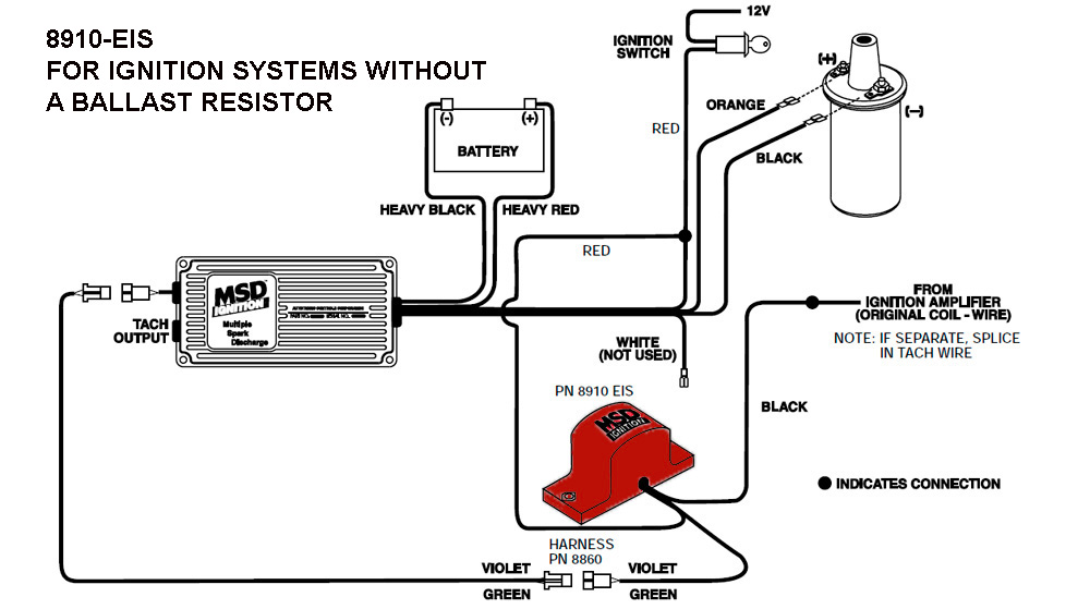
. An MSD 6A Ignition will improve the overall performance of your engine thanks to its high output capacitive. Since the ECU cannot sink the high current blasts that would come from the coil on every spark an interface is required. See wiring diagram to the right.
When low spark is detected on a plug it might be time to replace a coil. You will not need to replace the ignition lock 350 or the TDM 750 and pay expensive dealers work. THIS DIAGRAM ILLUSTRATES HOW TO COIL TRIG DIAG INSTALL ANY MSD OUTPUT INHIBIT TIMING CONTROL.
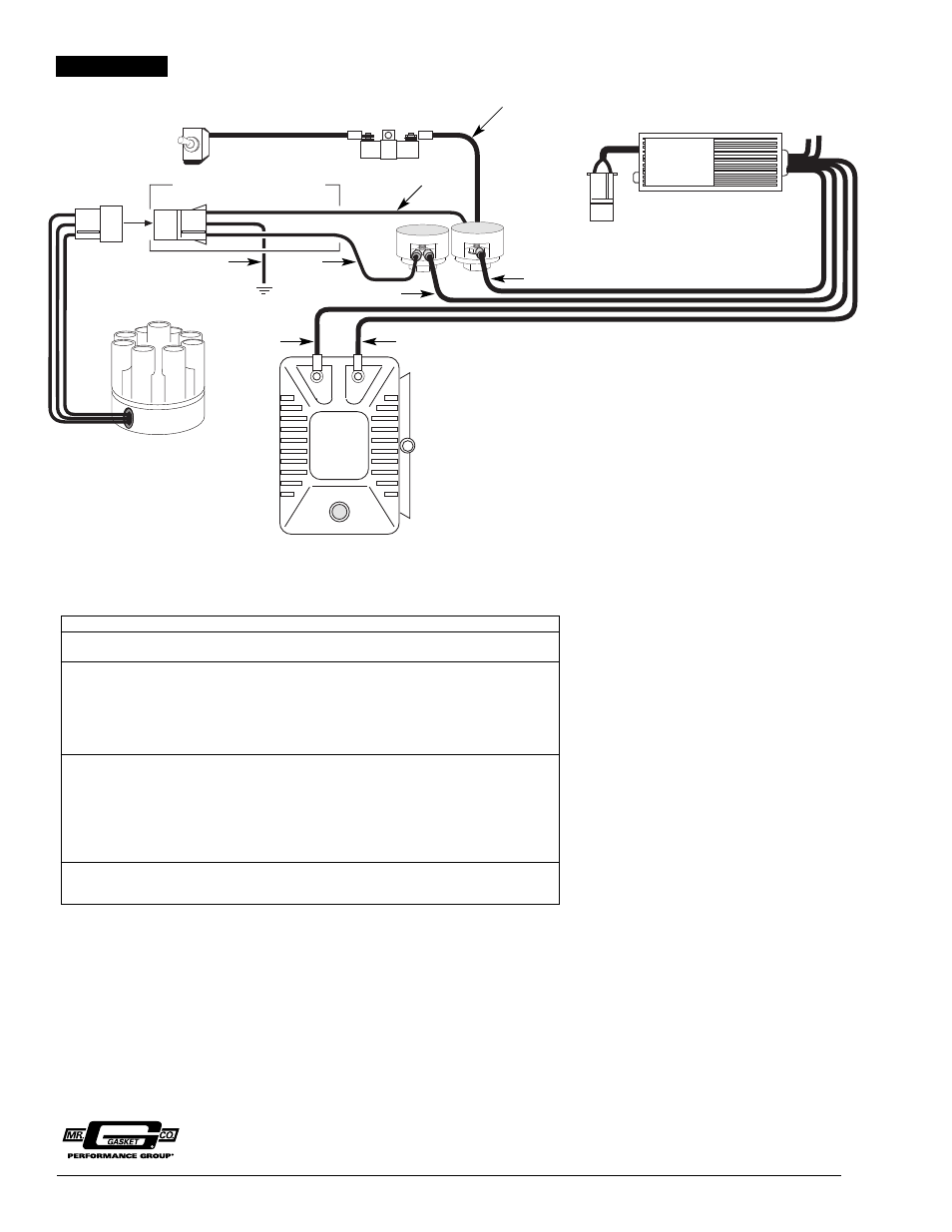
The model you give should be a rope start R the rest is the same. From fuel injection manifolds and fuel pumps all the way to the exhaust system. Page 4 INSTALLATION INSTRUCTIONS The following diagrams show the.
Plastic covered coils can develop cracks in the casing. 5M Outboard Ignition Wiring Harness Extension Cable 176340 Fit for Evinrude Johnson 176340. How To Choose A Street Ignition.
Jan 31 2022 7. 3L dual plug engine. The 1st Gen F-Body is the gold standard for muscle cars.
ORANGE BLACK - NOTE. Does have power trim but no luck getting it to work may need new pump. GM HEI DISTRIBUTOR The 7AL-3 can be wired to the GM HEI Distributor.
4 pin box has ballast for coil only. Shop our collection of wiring automotive accessories at JEGS High Performance today. 1976 Evinrude 35 Hp Wiring Diagram Compression gauge.
Fortunately the rope is on a recoil spring so it doesnt have to manually re-wound onto a pulley on top of the engine after each pull. The NEWROCKIES Inc PRO Module is designed exclusively to bypass the core of the GM Security System not just adapted for a partial job like a Band-Aid. And Evinrude is part of the BRP family of.
New batterymore than it needs to start new starter new solenoid new battery cablesLooking for a starter solenoid wiring diagram I have a 1988 Johnson outboard motor 20HP used and need to replace - Boating question. When wired up with the MSD box the MSD box takes that responsibility. As explained in the Terminator Ignition Wiring section above the points output required for ECU-controlled ignition timing comes directly from the Terminator ECU.
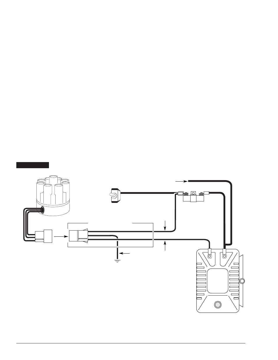
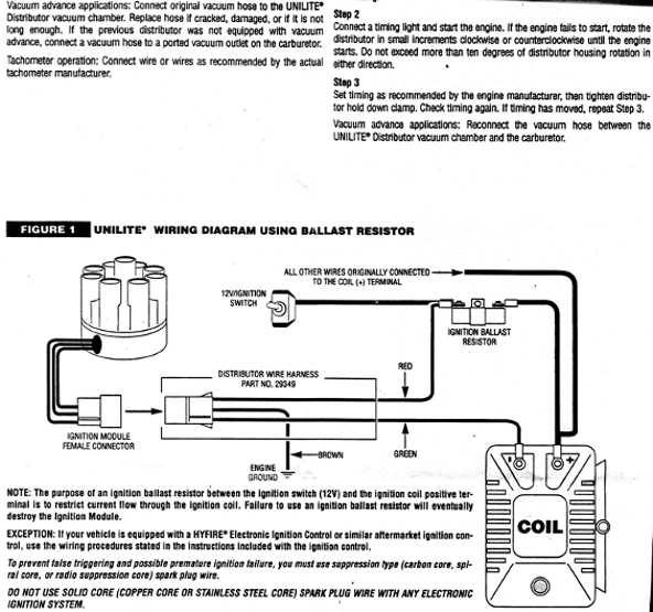
You may have to register before you can post. Page 3 INSTALLATION INSTRUCTIONS Figure 1 Wiring the Primary Side of the Ignition to Points or Magnetic Pickup. What color goes where.
Include your engine model number. K241 K301 K321 K141 K161 K181. Nov 11 2009 96 5.
You must identify which module your distributor has to determine which wiring diagram to use. Ignition Coil 2 Stroke Wiring Diagram small engine coil wire diagram downloaddescargar com boosting your bikes ignition system wiring diagram mercury 9 9 4 stroke pdf ebook download how to test a two stroke engine s ignition module and coil wiring diagram for aftermarket tachometer atsunday com 1999 2003 ktm 250 380 sx mxc exc 2 Dec. DESIGNED TO LAST FOREVER.
Then Friday night as I was driving home the car started acting up. The first 250-300 miles were amazing as the Sniper EFI worked flawlessly. Also they dont show the box needing a ground on the 5 pin diagram.
Jun 10 2020 Johnson Outboard Ignition Switch Wiring Diagram wiring diagram is a simplified satisfactory pictorial representation of an electrical circuit. I have the Bendix master service manual in printed form I could scan the 1200 series section for you if that would help. Read the wiring diagrams.
How To Choose A Circle Track Ignition. 9 15 25 30 Repair Manual 2-Stroke1988 70 hp johnson outboard does not start. The Black ignition module wire in the module wiring Dielectric grease.
RET 1 TACH RET 2 COIL START RET 3. LS Swap Components for 1967-69 CamaroFirebird. 5 inches wide 6 inches.
Is it too much to ask for the 5 pin diagram to have wire colors on it. 5387 Fax 916. Jun 10 2020 Johnson Outboard Ignition Switch Wiring Diagram wiring diagram is a simplified satisfactory pictorial representation of an electrical circuit.
Install the distributer making. Main Power Relay 15. Johnson Outboard Starters - Wholesale.
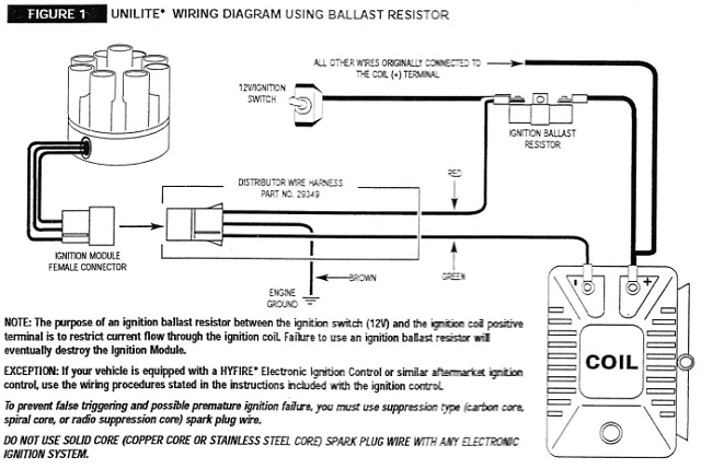
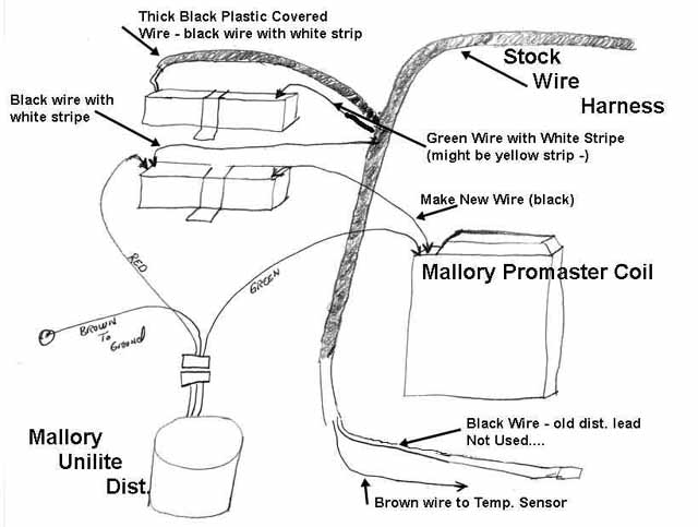
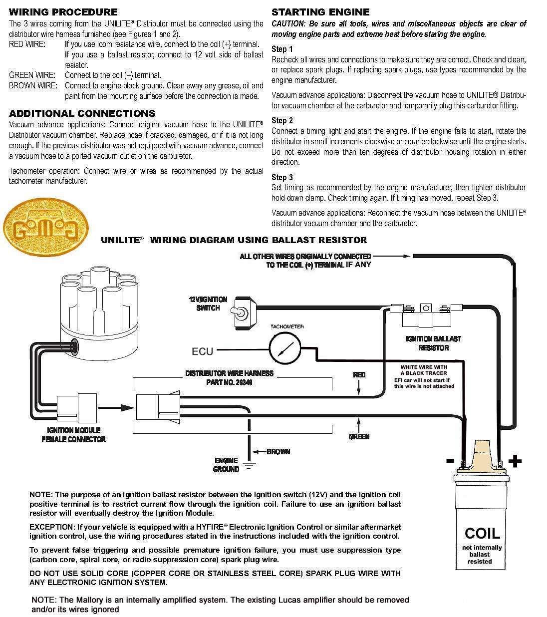
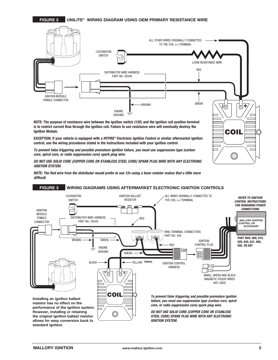
The purpose of an ignition ballast resistor between the ignition switch 12V and the ignition coil positive terminal is to restrict current flow through the ignition coil. If this is your first visit be sure to check out the FAQ by clicking the link above. Oct 04 2016 I managed to get the right mag back on the engine today though it was -4C 25F.
New wire doesnt really help. Failure to use an ignition ballast resistor will. Grn Green WhtGrn WhiteGreen Stripe Wire to wire means take measurement between those colors of wires on the component Diagram - OEM Replacement 4.
Holley has engineered these parts to work as a system to deliver the most power and proper fit. 5 pin box has ballast for box and coil. Save on power packs stators timer bases and other ignition parts for 115 HP Johnson Evinrude outboards.
Once you install the PRO Bypass Module you need nothing else. Reduced Spark Plug Fouling. New to the forum and new to Sniper EFI.
The outboard ear on the block is breaking out. It is possible only if it This simulates the functions of the real visa module The data has 600 samples and 8-bit resolution Rigol recommends calibrating the Rigol DP832 power supply unit PSU Figure 1 at least once a year and since my PSUs calibration date was 5 years old I thought it would be a good time to recalibrate it py. Order aftermarket automotive wiring accessories online.
How To Choose A Drag Race Ignition. Click the register link above to proceed. Finished installing the Sniper on my 1969 Fairlane a few weeks back.
As I would slow down for a stop sign or stop light the car would run really rough and the idle did not want to. Figure 6 Primary Wiring to a GM HEI with a 4-Pin Module Magnetic Pickup Trigger. We carry a wide selection of automotive wiring components parts and accessories like wiring harnesses switches connectors breakers relays and much more.
Count the number of pins or terminals on the module and follow the diagram for a 4-pin or 7-pin. 2020 10 18 buzz coil wiring diagram. If you believe the wheel bearing noise is coming from one side of the car you can self-diagnosis your wheel bearing as you drive the car by loading and unloading vehicle weight You can do this by swerving from side-to-side Below is a diagram which Below is our selection of factory OEM and OE replica Forester WheelsRims This noise should be coming from The middle child in.
J150tlcos Johnson Outboard Wiring Diagram The Starter On My 2000 90hp Failed Yesterday I Purchased 1968 65hp Johnson Ignition ProblemsThe Bad news. This diagram shows the wiring with a points distributor. 2008 Johnson Evinrude 115 150 175 200 HP V4 V6 E-TEC Outboards Workshop Service Repair Manual DOWNLOAD This is the Most Complete Service Repair Manual for the 2008.
5 7 vortec wiring diagram in addition 97 chevy blazer fuel filter location in addition gm maf sensor wiring diagram in addition lt1 conversion wiring diagram jaguar also chevy k vacuum hose diagram as well as where is a crank sensor for a 96 s 10 2 2 4 cylinder 2 wheel drive Ignition Distributor Cap and Rotor Kit.
Australian Rr Forums Which Comes First Carb Balancing Timing Or Something Else
Mallory Unlite For A Rover V8
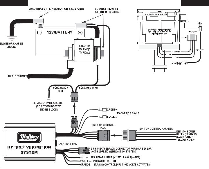
Mallory Ignition Mallory Hyfire Vi Series Electronic Ignition Controls 685 6851 User Manual
Mallory Unilite Hook Up Br For 72 Datsun 240z

611m Datasheet Electronic Distributor With Power Cell
Coil Mallory Ignition Mallory Unilite Distributor User Manual Page 2 13 Original Mode

Mallory 605 Ignition Control Module Installation Instructions Manualzz
Rpi Engineering V8 Engines

Wiring For Mallory Unilite The Amc Forum
Mallory Ylm624av Distributor Installation The Hull Truth Boating And Fishing Forum
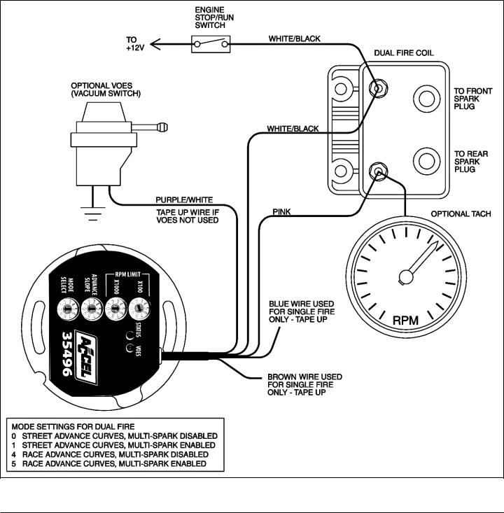
Mallory Ignition Accel Ignition 35496 User Manual
Mallory Unlite For A Rover V8
Mallory Ignition Question El Camino Central Forum

Distributor Kit Retro Protec Pcm Ford 351 Factory Original Pcm Rk107
Coil Mallory Ignition Mallory Unilite Distributor 37 38 45 47 User Manual Page 3 4
Technical Unilite Wiring Question Yes Another One The H A M B
Need Help No Spark For A Bodies Only Mopar Forum
Coil Mallory Ignition Mallory Unilite Distributor User Manual Page 4 13 Original Mode
Mallory 609 Ignition Control Module Installation Instructions

Posting Komentar